|
Artículo Científico / Scientific Paper |
|
|
|
|
https://doi.org/10.17163/ings.n28.2022.10 |
|
|
|
pISSN: 1390-650X / eISSN: 1390-860X |
|
|
COMPARATIVE ANALYSIS OF THERMAL COMFORT OF A SINGLE-
FAMILY HOUSE IN LSF AND BRICK MASONRY |
||
|
ANÁLISIS COMPARATIVO DE CONFORT TÉRMICO DE VIVIENDA UNIFAMILIAR EN LSF FRENTE A MAMPOSTERÍA |
||
|
Received: 16-05-2022, Received after review:
17-06-2022, Accepted: 20-06-2022, Published: 01-07-2022 |
|
Abstract |
Resumen |
|
Residential
construction in Ecuador has recently grown a 35.6%. The typical construction
system for housing envelopes is concrete block or brick; construction in
Light Steel Framing (LSF) or galvanized steel frames is emerging. To solve
the housing demand, the thermal comfort inside a two-story one-family home in
the city of Cuenca is evaluated considering both construction systems, to
know the comfort standards offered by homes in accordance with the Ecuadorian
Construction Standard (NEC, Norma Ecuatoriana de la
Construcción). The research was carried out with
Design Builder and Therm, where the parameters that
influence the energy performance of homes are analyzed. Under local
conditions, the predominant system reaches annual hourly thermal comfort
values of 51%, but the LSF system reaches 62%. However, with improvement
strategies in the overall envelope, the LSF reaches 86%. The variables in
decreasing order of thermal influence were: air infiltrations, envelope
construction system and housing deployment. In Cuenca it is feasible to use
the LSF with minimum insulation to reach acceptable levels of comfort, being
an adequate alternative to be promoted for building one-family housings. |
La construcción residencial en Ecuador ha crecido un 35,6 %. El sistema constructivo típico para envolvente de viviendas es de bloque de concreto o de ladrillo, la construcción en LSF (Light Steel Framing) o marcos de acero galvanizado (LSF) está en surgimiento. Para solucionar la demanda habitacional se evalúa el confort interior térmico de una de vivienda unifamiliar de dos plantas en la ciudad de Cuenca con ambos sistemas constructivos para conocer los estándares de confort que ofrecen las viviendas en concordancia con la Norma Ecuatoriana de la Construcción (NEC). La investigación se realizó con Design Builder y Therm donde se analizan los parámetros que influyen en el desempeño energético de las viviendas. Con las condiciones locales, el sistema predominante alcanza valores de confort térmico horario anual del 51 %, pero el sistema LSF alcanza un 62 %. Sin embargo, con estrategias de mejoramiento en la globalidad de la envolvente, el LSF alcanza el 86 %. Las variables en orden de mayor a menor influencia térmica resultaron: infiltraciones de aire, sistema constructivo de la envolvente e implantación de la vivienda. En Cuenca es posible el uso del LSF con aislamiento mínimo para alcanzar niveles aceptables de confort, siendo una alternativa adecuada a promover para edificar viviendas unifamiliares. |
|
Keywords: Housing, Light Steel Framing, Thermal
comfort, Simulation |
Palabras clave: vivienda, Steel frame, confort térmico, simulación |
|
1,* Dirección de Investigación de la Universidad de Cuenca, Universidad de Cuenca, Ecuador. Corresponding
author ✉: jrodrigo.britop@ucuenca.edu.ec. Suggested
citation: Brito-Peña, R.; Villa-Enderica, D. and Zalamea-León, E. “Comparative analysis of thermal comfort
of a single-family house in LSF and brick masonry,” Ingenius,
Revista de Ciencia y Tecnología, N.◦ 28, pp. 1-10, 2022, doi: https://doi.org/10.17163/ings.n28.2022.10. |
|
1. Introduction For each particular
context it is important to establish comparative analyses of different
construction technologies, to set capabilities in terms of security,
durability, quality, thermal comfort, among other aspects. It has been
evidenced that the thermal performance of dry construction systems such as
Lightweight Steel Framing (LSF) may reach conditions similar to those of
masonry [1], and it is possible to define insulation levels appropriate for
the context. According to the
American Institute of Architects (AIA, 2007), 50% of the worldwide emissions
of greenhouse gases were produced by the construction industry. To a large
extent, this is a consequence of the high consumption of buildings and the
lack of comfort in them. An impact is generated from the manufacturing,
transportation execution, use and maintenance of the building up to the end
of its life cycle [2]. Likewise, construction is placed as the second
industry with the highest energy demand worldwide, and most of such
consumption is used for achieving indoor environment tal
quality [3,4]. |
Therefore, it is
important to determine the capability of the construction materials to
achieve quality in thermal comfort with high degree of construction
efficiency [5, 6]. In the last fifteen years, the construction sector in
Ecuador has grown 35.6% due to the economic and population development. Among
the total number of construction permissions granted in 2018, 84.1%
correspond to residences, 56.9% correspond to one-family housings and 88.1%
are new housings. The predominant
materials for housings in Ecuador are reinforced concrete for foundations,
structure and roof, concrete block or brick masonry for walls and envelopes,
structured in steel for constructive speed. The introduction of alternative
construction systems is minimum, and very little consideration is given to
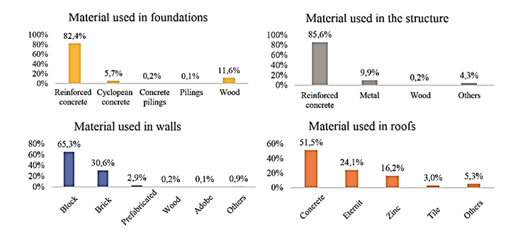
the affectations due to the materials selected. The housing in LSF dry
construction has a share of only 2.9 % in Ecuador [7], as seen in Figure 1
[7]. The systems that enable prefabrication are an opportunity to reduce the
construction cost, but the comfort levels should be also considered [8]. |
|
Figure 1. Main materials that predominate in the construction
in Ecuador |
|
|
The implementation of the LSF dry
system may result less offensive with the environment, and offers great
advantages compared to traditional wet systems regarding its in situ impact
[9]. Various constructive advantages are typical of this system, such as the
potential prefabrication and speed, durability, seismic-resistant capability,
convenient prices, among others [10]. The LSF has a good thermal performance
since it enables including the insulation required and calibrated according
to the local conditions; it has the capability of reaching high levels of
thermal insulation, even in extreme weather [11, 12]. In addition,
according to [9, 13], the main deficit regarding the thermal capacity in the
LSF is in the thermal bridges as a consequence of the light steel |
structural frames
which should not be more than 0.60 m apart. With respect to structural
capacity, the LSF has appropriate conditions due to the lower rigidity and
weight, which implies that the seismic response is adequate in regions of
high seismicity, such as the Andean zone [14, 15]. Likewise, it responds
favorably to accidental loads [16]. In terms of safety
in the event of fire, the LSF is recommended over other flame-retardant
technologies [17]. At the same time, it is capable of integrating all
components necessary to construct a building. The construction methods are
manufacturing on-site, by prefabricated panels and, finally, the modular
construction [18]. The LSF tends to be more expensive compared to masonry
housings typical in Ecuador, due |
|
to the reduced
penetration of the material. However, it may result a convenient system due
to the advantages of industrialization and market economy [19]. It reduces
the labor costs between 62.5% and 73%, and improves management of
consumables, operations and logistics at the construction sites [20]. In
Ecuador, the deficit in housings together with the difficult economic
situation causes the construction of low-budget buildings using handcrafted
materials, and those housings do not fulfill the appropriate levels of
thermal comfort, and thus, new buildings should meet NEC standards [21]. 1.1.
Climatic
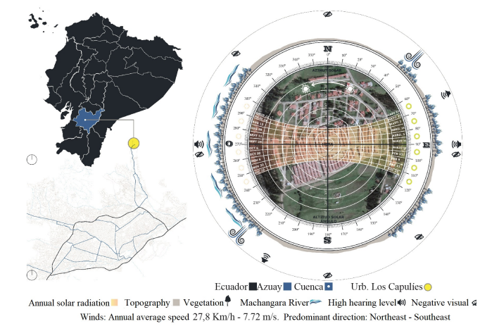
conditions of the surrounding of the housing under study Ecuador is divided in six climatic zones, according to what is established by the ASHRAE 90.1 and Miduvi [22]. The reference housing is located in climatic zone 3 of Ecuador, determined as a region of rainy continental mountains. Figure 2 shows a diagram |
of the climatic
conditions 3). The zone is very close to the Equator, at an altitude of 2550 m
above sea level; due to these conditions, it is a temperate and stable
climate all year round. The temperature varies between maximum and minimum
averages of 7 and 25 °C; however, extremes of –1.7 °C and 28.9 °C are
recorded, with an average of 15.6 °C. March is the hottest month and August
the coldest one, but the extreme conditions of cold or hot normally do not
last more than a few hours. Due to the Equatorian
conditions, seasonal climatic variations are minimal. The duration of the day
is also stable all year round, with the dawn occurring between 05:50 and 6:30
and the dusk between 18:05 and 18:35, depending on the season. The wind is
low, with preponderance from the Northeast. Consequently, it is about a
temperate weather with greater incidence of excessive cooling, but with a
weather benign for habitability; most buildings lack active conditioning
systems. However, this aspect implies that out of comfort moments are usual. |
|
Figure 2. Location and scheme of the
climatic conditions of the surroundings |
|
|
It
will be analyzed a housing with spatial and morphological features that are
recurrent in the country, with the most frequently used construction system
consisting of masonry and concrete, with the objective of determining the
base environmental conditions. On that basis, variations are compared
according to the change of envelope in the LSF construction system. For this purpose,
simulations are programmed
to contrast |
the thermal
behavior of the same housing materialized in two different construction systems
and envelopes, LSF system vs. traditional system, assuming the same
functional and spatial conditions. It is analyzed the type II model of
one-family housing found at the residential area Los Capulíes,
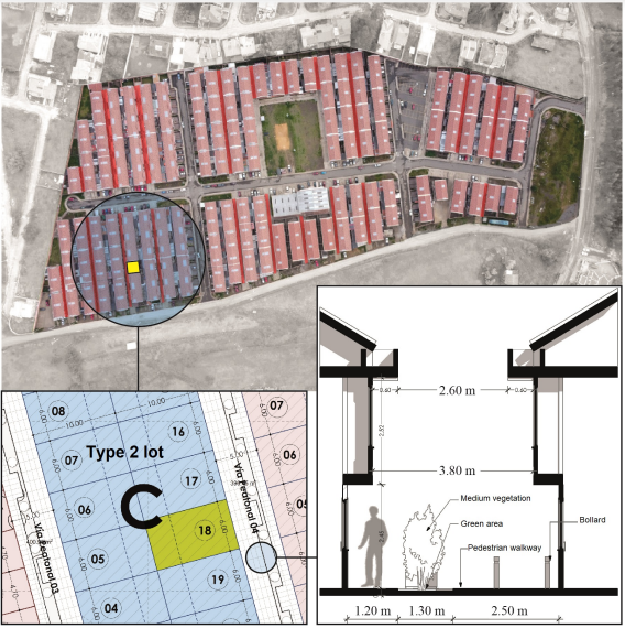
located at Cuenca, which was developed by the Housing Ministry (Miduvi, Ministerio de la Vivienda) of Ecuador. These housing |
|
are arranged
in high-density settings, paired on both sides to achieve a maximum leverage
of the piece of land. The distance between the fronts is only five meters,
whereas the backs are three meters apart. This arrangement reduces solar
incidence, and also causes |
visualization
and privacy problems. Figure 3 shows the configuration of the housings (based
on documents of the Emuvi EP). Even though it has
aspects regarding design conditions, this work analyzes the influence of
envelope materials. |
|
Figure 3. Housing under study
together with the remaining housings in the residential area Los Capulíes |
|
|
2.
Materials and
methods At first
instance, the parameters and features that have influence on energy
performance were established, and analyzed with respect to the levels of
thermal comfort of the regulation that dictates that the indoor temperature
should be maintained between 18 and 26 ºC [23]; it is considered that
excesses or deficits imply being out of the range of thermal comfort. With
this precedent, the following parameters were determined for studying energy
performance: Deployment: It is determined by the position of the housing within the block, corresponding to a corner, middle or isolated housing. Weather: It is deter- |
mined by means
of the climatological archive of the Cuenca region. Internal thermal gains:
It is referred to the amount of energy as heat within the housing,
contributed by electric appliances and users. Air infiltrations: Make
reference to the air exchanges per hour at a pressure of 50 Pa, i.e., to the
levels of air renewal inside a housing. These parameters
will be studied in three variations of the same housing, according to its
location within a block: isolated, middle and corner. Eighty-five models
were constructed for the analysis, from virtual variations of the materials.
The indoor operating temperature (OT) is considered the variable for the
analysis of results; the dry bulb external tem- |
|
perature (ET) only represents the
temperature that affects the housing envelope and enables reflecting the
level of conditioning reached by the housing. Regarding the levels of
infiltration of this type of structures, indicators found in Chile [24] are
considered since there are no local studies. Lower levels of air infiltration
(10 ACH50) are expected in the masonry envelope, compared to the 25 ACH50
expected in the LSF. However, when the LSF is constructed with greater
insulation, materials of better thermal performance and high construction
quality, with emphasis on the constructive joints, the air exchanges decrease
[25]. At a second
instance, digital models of the onefamily housing
to be studied were made in two groups. The recurrent configurations and
materials for the region, i.e., the traditional wet system, were modeled in
the first group. The models with the LSF system were made in the second
group. Finally, the indoor thermal comfort of the two construction systems
was analyzed at a third instance. Virtual models were studied with the Design
Builder [26] and Therm [27] energy simulators, fed
by 2016 climatic information of the region under study. The climatic file (. tmy) (typical average climate) was not used, because it
implies to lose days and hours with extreme temperatures; hence, it was used
climatic data corresponding to one year (2016) in the epw
file. The evaluation was
performed in sequential stages, due to the interaction of different factors
that have influence on the indoor thermal comfort. The first stage seeks to
determine the incidence of orientation, a diffuse aspect in the equatorial
weather. Prior to analyzing the thermal comfort of the housing, in the second
stage it is intended to determine with Design Builder the energy performance
of the housing with LSF, without including thermal insulation. The model is
fed by envelope coefficients from the thermal anal- |
ysis
of the materials carried out in Therm, tool that
enables to determine in detail the insulation capacity considering
affectations implied by thermal bridges. In the third stage it is sought to
know if there are improvements in the thermal levels with minimal insulations
in the LSF system. Finally, in the fourth stage it is sought to improve the
materials used in the LSF system, with the purpose of knowing if the thermal
increase is significant; thus, the Therm tool is
used again to analyze the configurations of the different carpentries. The
requency Thermal Discomfort (FDT) is the percentage
of time in which the operating temperature does not reach the required
standards [28]. Therefore, in this research the results will be analyzed as
percentages referred to a year in its 8760 associated hours. Likewise, the
parameters or variables with higher or lower incidence on the thermal
performance of the housing will be established in the final instance. 2.1.
Original feactures and materials of the housing under study The reference housing is a
two-story one-family housing of 86.40 m2 which, according to the INEC, is a
recurrent typology in the country. It is a housing with average size and
condition to accommodate four inhabitants. The housing is constructed with
steel structure, masonry brick walls for the envelope, with plaster only in
the interior and fiber cement roof with a false plaster ceiling parallel to
the fiber cement. The bottom and mezzanine floors are made of concrete, with porcelain
coating in wet areas and floating flooring in dry environments. Finally, the
carpentries are made of steel with simple glass. As a basis for comparison,
the indoor thermal quality is simulated with these conditions; Figure 4 shows
the reference housing. |
|
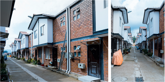
Figure 4. Status of the housing under study in 2020 |
|
|
The
LSF proposal adopts the same conditions of the base model. The structural
dimensions are provided by the engineering department of the local
distribution company. The recommended components are the following: Stud
profiles (columns) of 90 × 0.93 mm in walls and trusses, Track (beams) of 90
× 0.93 mm in walls and trusses, Stud of 200 × 1.8 mm in mezzanine floor and
Track 200 × 1,8 mm in mezzanine |
floor. However, the use and
configuration of the layers of insulation and coating materials are not
determined according to the thermal performance, due to the minimum use of
this technology nationwide. Both suppliers and consumers choose the
components and materials based on various criteria to build the housing.
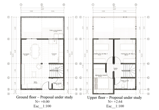
Figure 5 shows the plans of the housing adapted to LSF. |
|
Figure 5. Proposal materialized with LSF
|
|
|
2.2. General conditions for the indoor
thermal comfort study The aspects and
features of the envelope are identified as input data for the indoor thermal
comfort analy |
sis, and the parameters for
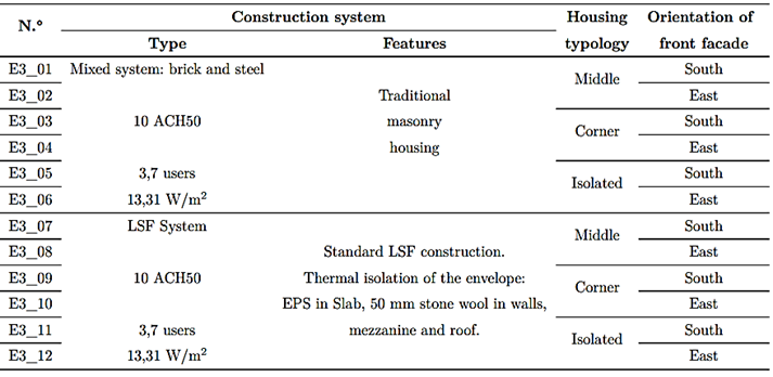
the digital evaluation are established categorized in six groups (Table 1). |
|
Table 1. General conditions and parameters
|
|
||||||
|
Figure 6. Average OT as a function of
the Deployment parameter |
|
|
3.1.1.
Analysis of
the thermal performance of the construction systems through the envelope
section by means of THERM The thermal
transmittance of each envelope material of the construction systems under
study, is analyzed in this section. The steel profiles that constitute the
structure of the entire housing are added to the traditional system; such
profiles are exposed in the original |
model. Likewise, the
LSF is considered with a simple insulation through a 50 mm thick single layer
of stone wool, with which there is a 40 mm remnant air layer in the envelope
section. The variable of study is the influence of the metallic structure in
each construction system. It is found the influence of the thermal bridges on
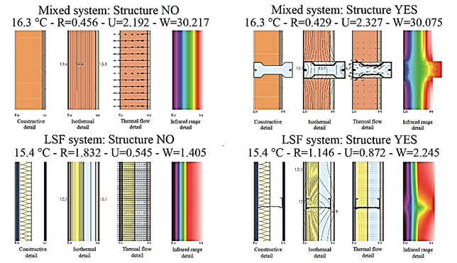
the housings. The most unfavorable cases of each orientation are analyzed, as
shown in Figure 7. |
|
Figure 7. Thermal analysis of the
section of both construction systems in THERM and conductivity determined |
|
|
High
values of thermal transmittance are evidenced in all the walls of the
envelope, the thermal bridges are important in both construction systems,
which significantly influences the insulation capacity. In the mixed
construction system constituted by bricks in steel porticoes, higher values
of thermal transmittance are observed in the zones in which structural
elements |
meet. However, in
the LSF, the thermal transmittance is spread and mitigated by the fiber
cement and plaster cardboard coating. |
|
3.2. Second stage: Thermal analysis
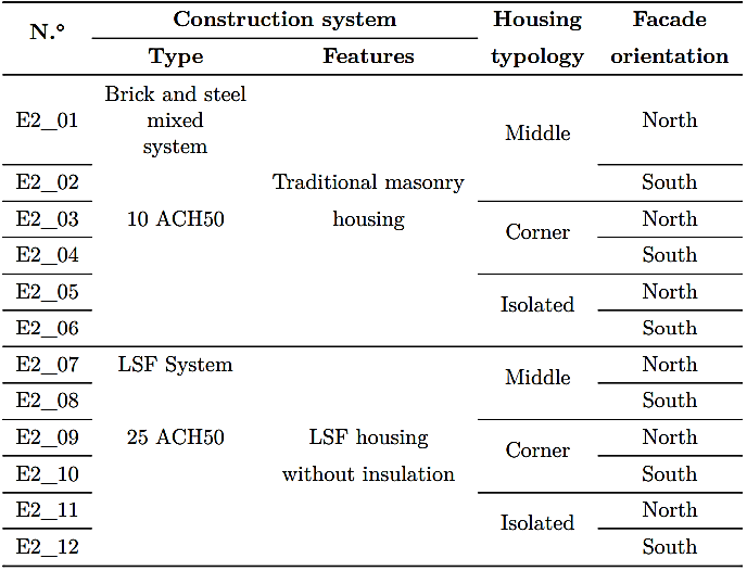
with incidence of the thermal bridges in unfavorable orientations At this stage (Table
3), the digital models are configured again in Design Builder, entering in the
simulator the new values of the Thermal resistance parameter or |
R Factor of
each material, values that are reduced to 67.78% of the original value
according to the study by means of THERM. In this section, the housings are
analyzed again with the condition of the Deployment parameter, referred in
this case to the most unfavorable orientations, i.e., without direct solar
incidence on facades. |
|
Table 3. Second stage
|
|
|
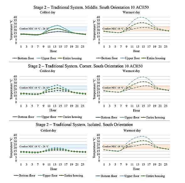
With
the brick and steel envelope, in the case of the coldest day the housing is
in comfort only at noon, whereas in the case of the warmest day, the comfort
occurs in the morning and in the afternoon. An important peak in high
temperatures is observed at noo |
Consequently, the
housing experiences overheating, since there is no insulation in the roof;
specifically, overheating in the upper floor, as observed in Figure 8. |
|
Figure 8. Thermal
comparison, traditional system, second stage |
|
|
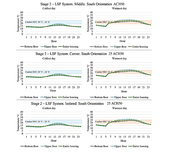
For the coldest day in the LSF system, there is comfort after noon. However, in the warmest day the comfort extends for almost all day long. It is observed that the thermal curve tends to reduce the oscillation during the 24 hours of the day. The maximum and |
minimum peaks are less pronounced than
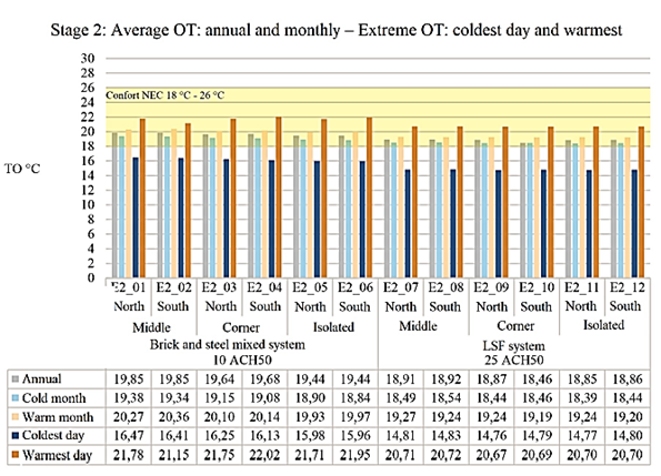
in the reference system, as it is seen in Figure 9. Figure 10 shows the
general thermal comparison of the second stage. |
|
Figure 9. Thermal comparison, LSF
system, second stag
Figure 10. General thermal comparison
for the second stage |
|
|
3.2.1.
Analysis of the
different inclusions of termal insulation in the
housings with LSF For the climatic features of the
Andean region in Ecuador, the «cold wall» [9] typology is used in the |
LSF analysis, as it is observed in
Figure 11 [9]. This wall typology with the insulation in the internal side
retains the heat in the interior in a better way, according to the analysis
with THERM. In addition, it is the simplest and the most economical. |
|
Figure 11. Wall
typologies: warm, cold and hybrid |
|
|
It
is also analyzed the incidence of the infiltrations estimated for the
constructive topology; according to the construction system, it has been
considered an ACH50 of 25, and from it, the consequent thermal performance of
the housing. The base housing (A01) shows the worst performance in average.
The A02 and A03 cases (A03 interior insulation is recommended by acoustic
conditions) are similar. However, the A03 housing implies a more hermetic
one, due to a better configuration of the surfaces of the envelope thermally
insulated in a more uniform manner. The air chamber produced between the roof
and the false ceiling of the upper floor provides better results with respect
to the |
base configuration, considering
that these housings are currently not constructed with false ceiling and,
much less, with insulation; hence, it is usual the overheating in the
presence of direct equatorial irradiation, as well as important thermal
losses at night. It is observed that the A04 and A05 cases are critical with
respect to the previous ones. This implies that it is necessary insulation in
the roof to a larger extent and in the floor to a lesser extent. From the 24
hours of the day, the results are quantified only at the hours that reach the
NEC comfort range (18 and 26 °C), as seen in Figure 12. |
|
Figure 12.
Types of insulation and energy performance in number of comfort hours |
|
|
3.2.2.
Analysis of the
energy performance of the different configurations of carpentries by means of
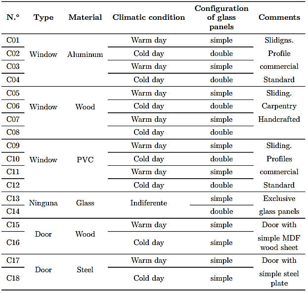
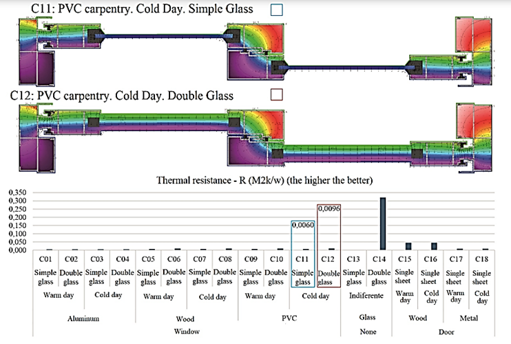
THERM The thermal bridges in the carpentries are also analyzed; the cases to be studied are presented in Table 4. Simulating only the glass panels without the influence |
of a carpentry, the insulation
capacity of the double glass panel (C14) is consistently higher compared to
the simple glass panel (C13). Therefore, a window with double glass and air
chamber is an improvement. With respect to the carpentry materials, wood or PVC
are adequate alternatives with good insulation features, as observed in
Figure 13. |
|
Table 4. Simulations of carpentries
|
|
|
Figure 13.
Results of the carpentries in days of extreme cold |
|
|
3.3. Third stage: Thermal
analysis of a housing with traditional materials vs a housing with LSF with
insulation At this stage, the indoor temperature under normal use conditions is checked through simulations. In addition, the deployment with the orientations; favorable (east) and unfavorable (south). In the case of LSF |
with the following variations:
Configuration of insulation, minor air infiltrations and carpentries. Table 5
shows the simulations. The housing with LSF uses the simulation solution A03
(perimeter insulation plus mezzanine). Therefore, the level of air
infiltrations decreases from 25 to 10 ACH50, data taken from the study by
(Madrid; Opazo; Parada, 2012). |
|
Table 5.
Conditions for Stage 3 of simulations
|
|
|
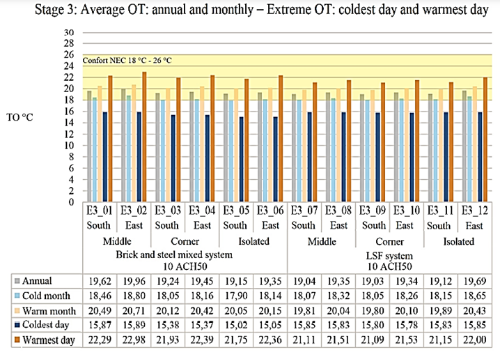
The
general result of every simulation indicates better thermal levels for both
construction systems. However, it should be remarked that the thermal gains
have been included. In this way, these are the thermal levels of the housing
with traditional system for daily |
use of its occupants. In the case of the LSF
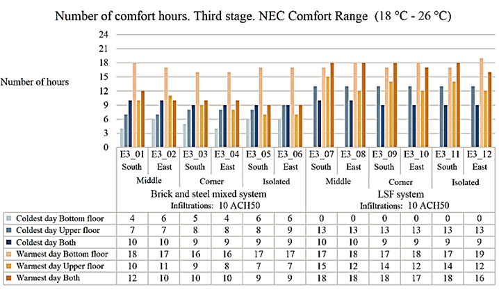
system the values are much better, as observed in Figure 14. With respect to
the number of comfort hours, Figure 15 shows detailed results. |
|
Figure 14. General thermal comparison for the third stage
Figure 15. Comparison of number of comfort hours for the third
stage |
|
|
A
comparison of the thermal levels of this simulation with the previous stage
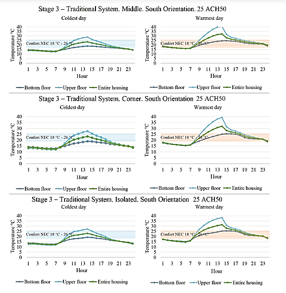
for the most extreme cases leads to the following comments. In the
traditional system, the actual one, the housing shows adequate indoor thermal
comfort 38 % of the time in a cold day, |
whereas low temperatures occur at
night and early morning. This percentage slightly raises to 42 % for the
hottest day, with overheating occurring from 10:00 to 18:00; this is mainly
due to the minimum insulation capacity of the roof, as observed in Figure 16. |
|
Figure 16.
Thermal comparison, traditional system, third stage |
|
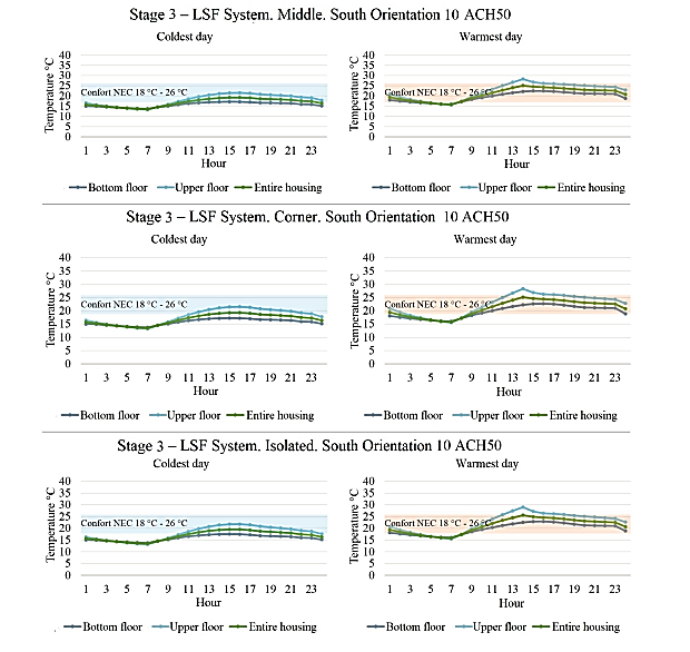
|
In
the LSF system, with the standard construction features established in Table
5, during the day the housing reaches indoor thermal comfort 38% of the time,
with temperature values between 13.47 °C and 19.52 °C. In the scenario of the
day with highest temperature, the housing reaches indoor thermal comfort |
in 67% of the hours, with a temperature range
between 16.53 °C and 26.89 °C. In the coldest and warmest day, the percentage
of daily comfort hours practically does not exceed 50% for both construction
systems, as it is observed in Figure reffigura17. |
|
Figure 17.
Thermal comparison, LSF system, third stage |
|
|
3.4. Fourth stage: Analysis of
the housing with LSF with the recommended construction features, with emphasis
on constructive quality and air infiltrations Once it is known the real
performance of the reference housing with masonry and steel structure
construction system (third stage), the LSF system is analyzed measuring the
possibility of increasing the annual comfort |
hours, adapting the system to
improve the constructive quality and the hermeticism
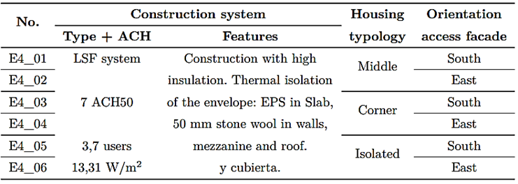
of the housing with high performance construction strategies (Table 6). In
this stage, an envelope adjustment to reduce infiltrations is considered,
assuming to reach 7 ACH50 (Table 6). Previous studies with LSF and wood
framework have established a reachable value of 7.47 ACH50 [31]. In parallel,
the International Energy Conservation Code (IECC) considers a value of 7
ACH50 |
|
Table 6.
Conditions for the stage 4 of simulations
|
|
|
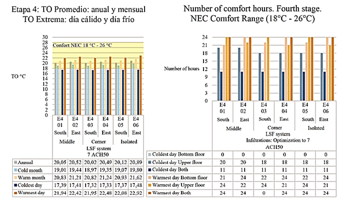
The
results point out that for the coldest day, as shown in Figures 18 and 19, the
values of Operating Temperature oscillate between 15.92 and 18.55 °C. The
differences between maximum and minimum values are minor. Consequently, it is
found that the fluctuations are minor. The increase in comfort hours, with
respect to the previous stage, goes from 38 to 46%, with infiltrations of 7
ACH50 with double glass windows. In the analysis of the warmest day, the val |
ues of operating temperature are
between 20.53 and 25.77 °C. The difference between the maximum and minimum
thermal values is considerably smaller than the reference housing. The
increase in comfort hours, with respect to the previous stage, goes from 67
to 100%. In the warmest day, an overheating is observed at the time of direct
solar incidence, which may be counteracted with natural ventilation due to
the lower external temperature. |
|
Figure 18.
Comparison of the thermal performance and of the number of comfort hours for
the fourth stage |
|
|
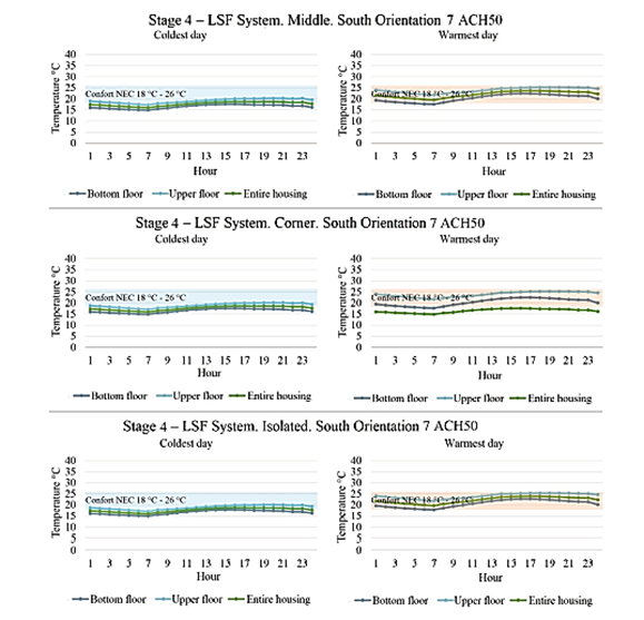
Figure
19 shows the housing with LSF in all orientations, where it is seen that the thermal
curve oscillates less throughout the day. The thermal variations are not very
pronounced, as it is evidenced in previous stages. With
the recommended construction strategies, |
considering the materials with the purpose of
reducing the levels of ACH exchanges, the thermal behavior of the housing is
more stable in temperature, without the need of using active heating systems. |
|
Figure 19.
Thermal comparison, LSF system, fourth stage
|
|
|
3.5. Discusión In the first stage, it is only
determined the most favorable and most unfavorable results, with respect to
the orientation of the housings. The orientation of the main facade with
openings of doors and windows facing towards the east and west is better
regarding thermal performance. However, the thermal variation is not
considerably smaller in the north-south orientation due to the dimensions of
the housing. In the second
stage, the results of unfavorable orientations (north-south) are observed on
the reference housing, where indoor thermal comfort is reached in only 27% of
hours throughout the year. The housing with LSF, without insulations in
subfloor and ceilings, |
always in the same orientations, reaches
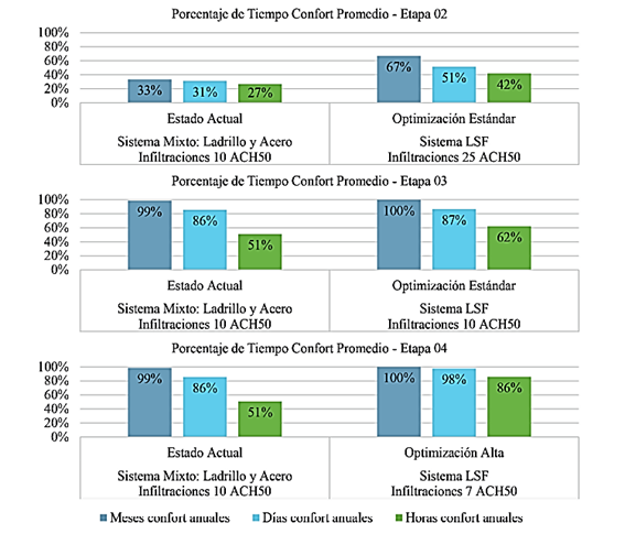
indoor thermal comfort 42% of the time. In the third stage, for the housings
in their current status the average percentage (under all orientations) of
hours in a year in indoor thermal comfort is 51%. This mainly occurs due to
the steel structure exposed both internally and externally, and by the
important losses in the roof without false ceiling. In addition, doors and
windows typically metallic also imply considerable thermal bridges. The
housings with LSF and standard optimization strategies to 10 ACH50 improve to
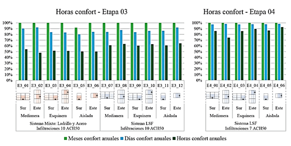
62% the number of comfort hours with respect to the base housing. In stage 4,
in Figures 20 and 21, for the housings with LSF with high optimization
strategies and infiltrations in 7 ACH50, the percentage of comfort time is
86%. |
|
Figure 20. Comparison of the number of
confort hours |
|
|
The results indicate
that the reference housing with traditional construction system has an
average minimum temperature of 15.38 °C and an average maximum temperature of
27.68 °C, both out of the NEC comfort range. However, when the housing has an
envelope in LSF with standard optimization strategies and with basic features
and isolation materials, the average minimum temperature improves slightly to
15.55 °C, without reaching the minimum of the standard, and the average
maximum temperature is 26.38 °C, slightly above the maximum of the standard.
Finally, for the housing in LSF with high optimization strategies, features
recommended by the analysis, the |
average minimum temperature is
17.19 °C, close to the 18 ºC established by the standard, and temperatures
above 26 ºC are not observed. At last, it is found that the parameter with highest
thermal incidence is the control of air infiltrations. Figure 21
shows an average comparative chart of the three housing typologies in a
unique monthly, daily and hourly average value. In this way, results are
shown as a function of the percentage of average time in which the housings
are in comfort. Average values are used, since it was demonstrated in each of
the stages that thermal variations of the housing typologies in minimal,
without exceeding 1 °C in most cases. |
|
Figure 21.
Comparison of the number of confort hours of all
stages |
|
|
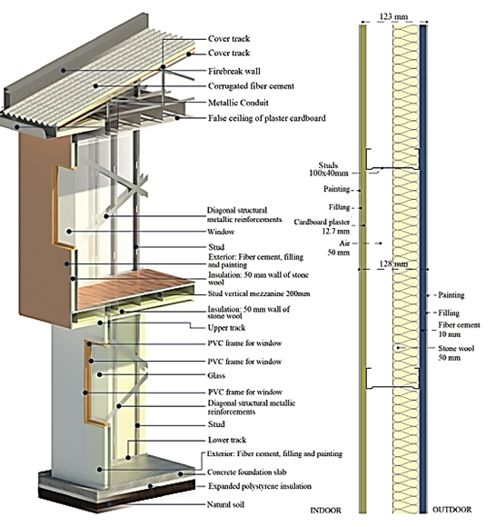
It is evidenced that the dimensions of the LSF section, stated according to the structural analysis, are more than enough to integrate the necessary insulation: 50 mm in stone wool placed between the studs, attached to the external side, leaving an air chamber of 50 mm between the studs, in a cold wall scheme. Then, |
the other parameters analyzed
arranged in decreasing order of importance include air infiltrations, material
of carpentries and, to a lesser extent, the orientation. Figure 22 shows a
scheme of the housing recommended with the new LSF system for the Andean
region. |
|
Figure 22.
Scheme of the proposal of the housing built with LSF |
|
|
4.
Conclusions This work carries out an analysis
with widely validated simulators, to detect comfort conditions and mismatches
in housings when changing and modifying the construction system, as well as
the comfort parameters. Once it is analyzed the modification of the envelope
from the traditional construction system using steel with brick envelope, it
is also analyzed the implications of the modification of the envelope and
other parameters such as orientation, infiltration and material of
carpentries. Even though these are simulations, it is the fastest way to be
able to analyze the different parameters in equal circumstances with the
modifications required. The comfort levels of the housings built with LSF are higher, compared to the reference housing built with the mixed construction system of brick masonry and structure with steel porticoes (traditional construction methodology). With the change in construction
|
system, the number of comfort hours
in the housing increases 11%, but a work with hermeticism,
change of material in carpentries, insulation in slabs, mezzanines and
ceilings, enables to reach 35% more hours within the comfort range. Although
the brick block as envelope material has better thermal inertia, the LSF
reaches appropriate levels of the envelope, even in the simple configuration
in sandwich wall. The most important variables for environmental performance, according to this study, arranged in decreasing order of thermal influence are: insulation in roof, mezzanine and foundation slab, the results indicate that horizontal insulations increase the percentage of comfort from 42 to 64%. Then, the parameter of air infiltrations through the hermeticism increases thermal comfort from 62 to 86%. Third, considering the housing material in general, together with the type of carpentries, the improvement of one system with respect to the other goes from 51 to 86%. The variables with lower incidence correspond to the deployment |
|
and typology
of the housings. These factors are due to the configuration and size of the
housings, since the dimensions are not big. The orientation, normally a
factor of great thermal incidence in other latitudes, for equatorial
locations the solar route causes that the irradiation incidence lasts few
hours. The results of the
analyses by orientation show that, in average, the indoor temperature is only
1 °C higher in the north – south orientation, and even welloriented
housings receive little direct solar radiation on the facades due to the
minimal separation between housings because of the grouping conditions. With the
proposed configuration of materials, it is feasible to build a housing in the
city of Cuenca with habitability conditions within the thermal comfort range
between 18 °C and 26 °C. Consequently, it is adaptable to various cities in
Colombia, Ecuador and Peru that are in equatorial conditions at a height
close to 2500 m above sea level. However, for more extreme weather it is
necessary to check the envelope adaptability. The change of
materials not only seeks to generate housing that are comfortable for final
users, but it also seeks, as indicated by sources consulted, to reduce the
environmental and ecological impact generated by the construction industry
with handcrafted processes, many of them with no control, avoiding
unnecessary wastes and saving resources that are increasingly scarce, before,
during and after the construction. References
[1] V. Arengo Piragine, J. Cruz Breard, and C. Pilar, “Anteproyecto de viviendas sociales con steel framing en corrientes. comparación con sistema húmedo tradicional,” Arquitecno, no. 15, p. 37, 2020. [Online]. Available: http://dx.doi.org/10.30972/arq.0154386 [2] A. O. Venegas Tomalá, Evaluación de la energía contenida, emisiones de CO2 y material particulado en la fabricación del ladrillo semimecanizado tochano en Cuenca, a través del análisis de ciclo de vida (ACV). Universidad de Cuenca, Ecuador, 2018. [Online]. Available: https://bit.ly/2Soq1IU [3]
M. T. Baquero L. and F. Quesada M., “Eficiencia energética en el sector
residencial de la ciudad de Cuenca, Ecuador,” Maskana,
vol. 7, no. 2, pp. 147–165, 2016. [Online]. Available: https://doi.org/10.18537/mskn.07.02.11 [4] M. Manzan,
E. Zandegiacomo De Zorzi,
and W. Lorenzi, “Numerical simulation and
sensitivity analysis of a steel framed interna
insulation system,” Energy and Buildings, vol. 158, pp. 1703–1710,
2018. [Online]. Available: https://doi.org/10.1016/j.enbuild.2017.11.069 |
[5]
M. Bernardes, S. G. Nilsson,
M. S. Martins, and A. Romanini,
“Comparativo econômico da aplicação
do sistema light steel framing
em habitação de interesse social,” Revista de Arquitetura
IMED, vol. 1, no. 1, pp. 31–40, 2012. [Online]. Available: https://doi.org/10.18256/2318-1109/ arqimed.v1n1p31-40 [6] L. M. Lupan, D. L. Manea, and L. M. Moga, “Improving thermal performance of the wall panels using slotted steel stud framing,” Procedia Technology, vol. 22, pp. 351–357, 2016. [Online]. Available: https://doi.org/10.1016/j.protcy.2016.01.108 [7] INEC. (2017) Encuesta de edificaciones 2017. Instituto Nacional de Estadísticas y Censos del Ecuador. [Online]. Available: https://bit.ly/3NsvnyW [8] MIDUVI, NEC-11. Vivienda De
Hasta 2 Pisos Con Luces De Hasta 4.0 M. Ministerio de Desarrollo Urbano y
Vivienda. República del Ecuador., 2011. [Online].
Available: https://bit.ly/3HU0uCk [9] E. Roque and
P. Santos, “The effectiveness of thermal insulation in lightweight
steel-framed walls with respect to its position,” Buildings, vol. 7,
no. 1, 2017. [Online]. Available: https://doi.org/10.3390/buildings7010013 [10] A. M. Sarmanho Freitas and R. C. Moraes de Crasto, Steel Framing: Arquitectura. Instituto Latinoamericano del Fierro y el Acero - ILAFA, 2007. [Online]. Available: https://bit.ly/3QOMYUy [11] J. L. Lamus
Rodríguez, “Análisis de viabilidad económica: sistema constructivo light steel framing en Colombia,” Master’s thesis, Universidad de
los Andes. Colombia, 2015.
[Online]. Available: https://bit.ly/3HRQfhU [12] E.
Rodrigues, N. Soares, M. S. Fernandes,
A. R. Gaspar, Álvaro Gomes, and J. J. Costa, “An integrated energy
performance-driven generative design methodology to foster modular
lightweight steel framed dwellings in hot climates,” Energy for
Sustainable Development, vol. 44, pp. 21–36, 2018. [Online]. Available: https://doi.org/10.1016/j.esd.2018.02.006 [13] B. Schafer, D. Ayhan, J. Leng, P. Liu, D.
Padilla-Llano, K. Peterman, M. Stehman, S. Buonopane, M. Eatherton, R.
Madsen, B. Manley, C. Moen, N. Nakata, C. Rogers, and C. Yu, “Seismic
response and engineering of cold-formed steel framed buildings,” Structures,
vol. 8, pp. 197–212, 2016. [Online]. Available: https://doi.org/10.1016/j.istruc.2016.05.009 |
|
[14] T. Tafsirojjaman, S. Fawzia, D. Thambiratnam, and X. Zhao, “Seismic strengthening of rigid steel frame with cfrp,” Archives of Civil and Mechanical Engineering, vol. 19, no. 2, pp. 334–347, 2019. [Online]. Available: https://doi.org/10.1016/j.acme.2018.08.007 [15] J. R. da Silva Nogueira, I. J. Apolônio
Callejas, and L. Cleonice Durante, “Desempenho de painel de vedação
vertical externa em light steel
framing composto por
placas de madeira mineralizada,” Ambiente Construido, vol. 18, no. 3,
2018. [Online]. Available:
https: //doi.org/10.1590/s1678-86212018000300282 [16] F. Bolina, R. Christ, A. Metzler, U. Quinino,
and B. Tutikian, “Comparison of the fire resistance
of two structural wall systems in light steel framing,” DYNA, vol. 84,
no. 201, pp. 123–128, abr. 2017. [Online]. Available: https://doi.org/10.15446/dyna.v84n201.57487 [17] E. Yandzio,
R. M. Lawson, and A. G. J. Way, Light steel framing in residential
construction. SCI. Silwood Par, Ascot,
Berkshire, 2015. [Online]. Available: https://bit.ly/3xXZhoV [18] P. E. Amador Salomão, A. D. Alves Soares, A. L. P. Lorentz, and L. T. Gonçalves de Paula, “Conventional masonry and light steel framing comparative analysis: a case study in unifammary residence in teófilo otoni, mg,” Research, Society and Development, vol. 8, no. 9, p. e14891268, Jun. 2019. [Online]. Available: https://doi.org/10.33448/rsd-v8i9.1268 [19] H. OlivieriIvan, I. C. Alves Barbosa, A. C. Da Rocha, A. Denis Granja, and P. S. Pucharelli Fontanini, “A utilização de novos sistemas construtivos para a redução no uso de insumos nos canteiros de obras: Light steel framing,” Ambiente Construido, vol. 17, no. 4, 2017. [Online]. Available: https: //doi.org/10.1590/s1678-86212017000400184 [20] MIDUVI, Acuerdo Ministerial: Reglamento para validación de tipologías y planes masa para proyectos de vivienda de interés social. Ministerio de Desarrollo Urbano y vivienda. República del Ecuador, 2019. [Online]. Available: https://bit.ly/3HSg3ul
|
[21] ——, Eficiencia energética en edificaciones residenciales NEC-HS-EE. Ministerio de Desarrollo Urbano y vivienda. República del Ecuador, 2018. [Online]. Available: https://bit.ly/39U5CtD [22] ——, Eficiencia energética en la
construcción en Ecuador. Ministerio de Desarrollo Urbano y vivienda. República del Ecuador, 2011. [Online].
Available: https://bit.ly/39QqLoM [23] Intergovernmental Panel on Climate Change, Summary for Policymakers. Cambridge University Press, 2014, ch. Climate Change 2013 – The Physical Science Basis, pp. 1– 30. [Online]. Available: https://doi.org/10.1017/ CBO9781107415324.004 [24] S. A. Navarrete Boutaud,
Impacto de las infiltraciones de aire en el desempeño energético y térmico
de las viviendas. Universidad
de Concepción. Chile, 2016. [Online]. Available: https://bit.ly/3QSwxqg [25] Design Builder. (2022) Design
builder software. [Online]. Available: https://bit.ly/3OnQ8gp [26] Berkeley Lab.
(2022) THERM. Windows and Daylighting. [Online]. Available: https:
//bit.ly/3HU2iv6 [27] J. Roset Calzada, R. A. Vásquez Paredes, and L. M. Barajas Saldaña, “ús eficient de programes informatics en arquitectura: Designbuilder i Dialux,” JIDA’14. II Jornadas sobre Innovación Docente en Arquitectura, 2014. [Online]. Available: https://doi.org/10.5821/jida.2014.5027 [28] INEC. (2011) Vii censo de población y vi de vivienda. Instituto Nacional de Estadíticas y Censos. [Online]. Available: https://bit [29] H. Madrid, F. Opazo, and O. Parada, “Impacto de las
infiltraciones de aire en el desempeño energético y térmico de las
viviendas,” Construciión, 2012. [Online]. Available: https://bit.ly/3yn1Gev [30] E. Roque and
P. Santos, “The effectiveness of thermal insulation in lightweight
steel-framed walls with respect to its position,” Buildings, vol. 7,
no. 1, 2017. [Online]. Available: https://doi.org/10.3390/buildings7010013 [31] The U.S. Department of Housing and Urban Development Office of Policy Development and Research, Steel vs. Wood. Cost Comparison. Beaufort Demonstration Homes. Partnership for Advancing Technology in Housing, 2002. [Online]. Available: https://bit.ly/3ngPhCz
|
